
These are notes of mine about making my interpretation for the Oseberg Queen's burial Thread Winder.
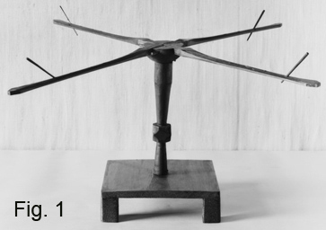
The original was made of beech wood and I did the same. I chose straight grained wood as this was the normal use of wood at the time, specifically that wood was split from the tree and wood workers would use the pattern of the grain for it's strength. Curved items would use limbs that would have similar grain.The black and white photo on the right, which is the museum's reproduction, shows a square base which appears as a board on four square legs. A person needs to understand that museums normally will not speculate when replacing parts and would most likely construct something that is functional only. The thickness of the board was likely gauged by the length of the tenon and it's pin, as I will discuss later.
I do not discuss detail on the base, as this is your choice. Make it as I did, as the museum did, or make your own.
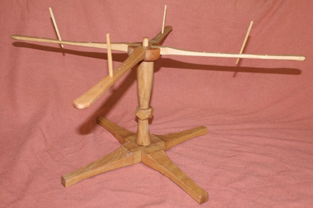
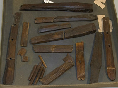
 On the left you see the unassembled parts, including my parts for the base. As stated, this base is conjecture only. As we will be using the tool in reenacting, I chose to construct a base that would pass as "probable" in the sense of reconstructing a lifestyle for public education.
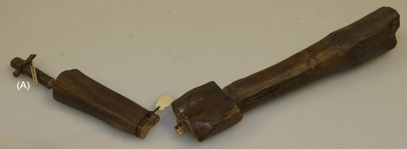
On the end of my shaft you see a peg that looks similar to the one in the museum's original parts,(to the right.) but they are NOT the same. In my reproduction I replaced that piece with a square mortise and the center pivot pin on the top would have been smaller diameter, indicated only by the hole in the rotating hub. My center pivot is wider than the original.
The blades of the swift have different tips, not carved to be identical yet not specific in design. I would refer it to "casual carving".
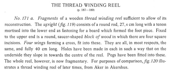 From the original text.
 The museum's reproduction (Fig. 1) appears to have been turned on a lathe. Close observation of the shaft gives me the impression that the original was carved, not turned as there are irregularities that appear consistent with carving. Even considering differential shrinkage or soil deformation, I do not believe the shaft was turned.
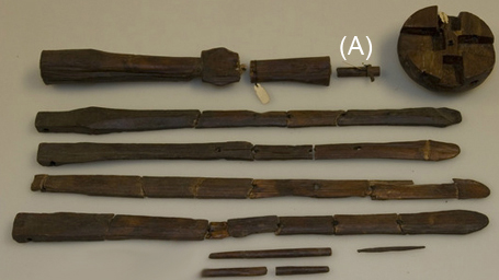
Again, the small diameter dowel with a pin through the end is referred to as a mortise used to fasten the bottom of the shaft to a board. NO evidence of the center pivot pin that permitted the hub to rotate has been indicated. The hole that remains in the hub is smaller diameter than the "mortise" I labeled (A).
 This is a close up of the blades. Though broken, you can see the different tip ends and where the blades were mounted into the hub. Also, the top blade is sideways and you can see the hole that the wood nails were passed through, fastening the blades to the hub.
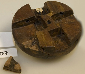 Note the small hole in the center of the hub. This is too small for the pin marked (A).
On the sides of each carved inlet you can see how the wood nails were drilled through the hub to fasten the blades.
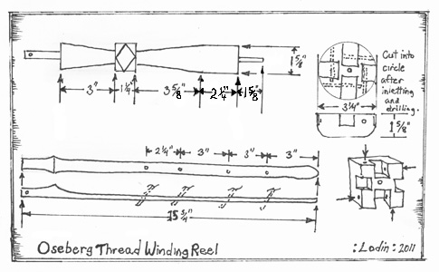
On the right are some measurements I used to make my reproduction. Some of the measurements are approximations made by comparing known measurements against other parts. As noted in the schematic, it is best to cut the hub as a square block, shape the inletted slots and drill the wood nail holes for fastening the blades to the hub. When the blades are ready, clamp each blade in it's respected hole and drill through the pre-drilled hole to make them ready for assembly. REMOVE the blades, use a coping saw, saber saw or band saw to make the hub round, then reinsert the blades, glue and pin. The protruding wooden pins can be cut off with a saw or knife.
Finish as desired.